
Yokohama Fender: The Floating Pneumatic Buffer That Protects Mega-Ships at the Berth
05/11/2026
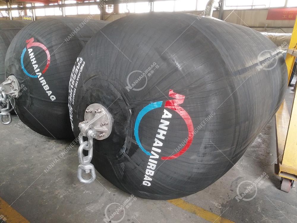
Pneumatic rubber fenders are floating, air-filled marine fenders that absorb berthing impact by compressing sealed air inside a reinforced rubber body. Built to ISO 17357-1:2014, they deliver high energy absorption with low, progressive reaction force—protecting both hull and quay during ship-to-ship (STS) transfer, tidal ship-to-dock (STD) berthing, LNG/crude offloading, FPSO operations, and naval mooring. Available in P50 (50 kPa) and P80 (80 kPa) pressure classes, with net-type or sling-type exteriors, they float at the waterline and track tide, swell, and hull movement. Unlike marine airbags, which launch or lift a vessel, pneumatic rubber fenders are continuous berthing buffers in the marine fenders family—and unlike solid rubber fenders, they conform softly to angled contact instead of pushing back hard.
If you operate a terminal, STS transfer, or tidal berth, the difference between a clean approach and a hull-denting impact often comes down to one variable: how the fender behaves in the first 30% of compression. Keep reading—because most berth damage isn’t caused by “the wrong size fender,” it’s caused by picking a fender on diameter alone instead of on energy, reaction force, and hull pressure.
What Is a Pneumatic Rubber Fender?
A pneumatic rubber fender—also called a Yokohama-type fender or floating pneumatic fender—is essentially a reinforced rubber air spring for ships.
Instead of crushing solid rubber, the hull compresses sealed air. The body is built in four integrated layers:
- Outer rubber – abrasion, UV, ozone, and seawater resistance
- Synthetic tire-cord plies – angled nylon/polyester reinforcement, the pressure-carrying skeleton
- Inner rubber liner – airtight sealing membrane
- End flanges + safety relief valve – inflation, lifting, and automatic over-pressure release (mandatory for bodies ≥ Ø2500 mm)
The result: when a vessel makes contact, internal pressure rises uniformly, kinetic energy converts to air compression and elastic cord strain, and reaction force stays low and stable. When the vessel backs off, the fender re-expands.
Why Pneumatic Fenders Outperform Solid Alternatives
Here’s where the product earns its place on a busy berth. The advantages aren’t cosmetic—they change how a terminal handles large vessels.
1. Low reaction force protects sensitive hulls
Solid cone or cell fenders get stiff fast as they compress. A pneumatic fender stays soft at first contact, then ramps up gradually.
At 60% deflection (the ISO 17357 test point), a 3300 × 6500 mm P50 fender absorbs about 1814 kJ while keeping reaction near 3015 kN. The P80 version of the same size jumps to 2532 kJ / 3961 kN .
Example:
An LNG carrier or aluminum-hulled cruise ship has strict allowable hull-surface pressure. A pneumatic fender spreads load across a wide contact patch instead of creating local stress points that can buckle plating.
2. It floats—and tracks the tide automatically
Fixed rubber fenders bolt to the quay. When water drops, they stop protecting the lower hull.
A pneumatic fender sits at the waterline. As tide, swell, trim, and draft change, it stays in the contact zone—no adjustable brackets, no repositioning.
Example:
A tidal terminal with a 5-meter range can berth the same vessel at high and low water without moving hardware. The fender rises and falls with the hull.
3. Angled berthing doesn’t kill performance
Real berthing is rarely perfectly square. Vessels come in skewed, rolling, and pitching.
Pneumatic fenders maintain energy absorption under inclined compression far better than solid profiles, which lose efficiency and need oversizing for angled contact .
Example:
In a cross-current STS transfer, the fender compresses asymmetrically without bottoming out or throwing a hard reaction spike back into the hull.
4. Soft entry, stable under overload
The force-deflection curve is nonlinear: easy at first contact, stronger only as needed.
That means:
- less hull rebound,
- lower mooring-line shock,
- safer behavior in swell and surge,
- predictable performance even if the vessel approaches harder than planned.
Example:
A supply vessel drifting into an offshore platform in 1.5 m swell gets absorbed gradually instead of bouncing off a rigid cell fender.
5. Portable, deflatable, redeployable
When deflated, a pneumatic fender folds down for container shipping—cutting transport volume versus foam or solid units .
That makes it ideal for:
- project-based STS operations,
- emergency lay-by fenders,
- charter fleets,
- salvage cushioning,
- terminals that don’t want permanent fender lines.
Types of Pneumatic Rubber Fenders
Type I – Chain-Tire Net (CTN)
Heavy galvanized chain or wire mesh with tires/rubber sleeves wrapped around the body.
- ✅ Maximum abrasion resistance
- ✅ Protects rubber skin from sharp quay debris
- ✅ Default for VLCC/LNG STS, oil terminals, rough seas
- ⚠️ Can leave tire marks on sensitive hulls
Sizes commonly from Ø500 mm up to Ø4500 mm .
Type II – Sling Type
No hard net. Thick outer rubber with integral lifting slings or eyes.
- ✅ Lightweight, fast to deploy
- ✅ Non-marking options available
- ✅ Ideal for yachts, cruise, naval, calm-water temporary berthing
- ⚠️ Less abuse-tolerant than CTN
Hydro-Pneumatic Variant
Part air, part water ballast (~60–70% water). Held submerged for low-freeboard contact.
- Submarine tendering
- Naval sub-surface ops
- Special low-hull-pressure applications
Always custom-engineered, never off-the-shelf guesswork.
P50 vs. P80: Same Size, Two Personalities
| Rating | Initial pressure | Reaction force | Energy absorption | Best use |
|---|---|---|---|---|
| P50 | 50 kPa | Lower | Standard | LNG, aluminum hulls, yachts, naval, sensitive structures |
| P80 | 80 kPa | Higher | ~35–40% more | VLCC STS, high approach speed, limited fender count |
⚠️ Never inflate a P50 body to 80 kPa. Cord angle, end-ring rating, and safety factor differ between classes .
Typical Sizes & Performance (ISO 17357-1, 60% deflection)
| Size (D × L) | P50 GEA | P50 Reaction | P80 GEA | P80 Reaction |
|---|---|---|---|---|
| 1000 × 1500 mm | 32 kJ | 182 kN | 45 kJ | 239 kN |
| 2000 × 3500 mm | 308 kJ | 875 kN | 430 kJ | 1150 kN |
| 2500 × 5500 mm | 943 kJ | 2019 kN | 1317 kJ | 2653 kN |
| 3300 × 6500 mm | 1814 kJ | 3015 kN | 2532 kJ | 3961 kN |
| 4500 × 9000 mm | 4755 kJ | 5988 kN | 6633 kJ | 7551 kN |
GEA = Guaranteed Energy Absorption. Tolerance typically ±10%; always use the supplier’s certified curve for design.
Pneumatic Rubber Fenders vs. Other Marine Protection Gear
This is the comparison every procurement team needs before checkout.
| Product | Job | Load type | Floats? | Key strength |
|---|---|---|---|---|
| Pneumatic rubber fender | Berthing impact buffer | Dynamic kinetic energy | Yes | Low reaction, tidal tracking |
| Solid rubber fenders (cone/cell/arch) | Fixed quay protection | Impact + compression | No | Zero maintenance, high traffic |
| Foam-filled fender | Floating buffer, no pressure upkeep | Impact | Yes | Puncture-proof, unsinkable |
| Marine airbags | Launch, haul-out, lift, salvage | Quasi-static weight/buoyancy | When inflated | Moves the vessel, not cushions it |
A complete marine program often uses all of them:
- marine airbags get the hull into the water,
- pneumatic rubber fenders protect it during STS/STD contact,
- fixed rubber fenders guard the quay face.
They are never interchangeable. An airbag is not a berthing fender, and a pneumatic fender is not a launch roller .
How to Specify a Pneumatic Rubber Fender (Without Getting Burned)
A vague PO line like “supply 3 m fender” is how terminals end up with the wrong reaction force.
Minimum compliant specification
Pneumatic rubber fender, ISO 17357-1:2014, P50, Ø3300 × L6500 mm, Type I chain-tire-net, with safety relief valve, mill certificate and third-party class approval (ABS / BV / DNV / CCS / LR).
Step 1: Calculate berthing energy (not DWT)
Use the PIANC method:
E = ½ × Mₑ × V² × Cₑ × C_m × C_s × C_c
Where:
- Mₑ = effective vessel mass
- V = approach velocity
- Cₑ, C_m, C_s, C_c = eccentricity, added-mass, softness, and configuration coefficients
Then select a fender where GEA at 60% deflection ≥ design energy × 1.1–1.25 safety margin .
Step 2: Check reaction force and hull pressure
Reaction force must stay within:
- wharf foundation limits,
- hull-panel allowable pressure (PIANC WG-211 suggests <200 kN/m² for gas carriers) .
Step 3: Pick P50 or P80 by hull sensitivity
Sensitive hull → P50. High energy, limited fenders → P80.
Step 4: Pick net or sling by duty
- CTN for abrasive, high-traffic, heavy STS
- Sling for yachts, naval, clean coatings
Step 5: Verify certification
Require:
- ISO 17357-1:2014 compliance
- Prototype + production test reports
- Cord specification and rubber material tests
- Relief valve on fenders ≥ Ø2500 mm
- Body marking: standard, size, pressure, serial no., maker, year
⚠️ “PIANC-certified” is marketing noise—PIANC writes design guidelines, not product certification. Require ISO data + class reports instead .
Installation: The Details That Decide Service Life
- Horizontal spacing: 1.5–2.0× fender length so contact is shared
- Bottom of fender: ≥300 mm above low water
- Suspension: balanced vertical hang, rated shackles/swivels, no welded repairs
- Chain slack: enough for tide, not so much the fender drifts
- STS freeboard differential: calculate before rigging to avoid fender climb
- Safety valve: accessible, calibrated, never painted over
Maintenance and Inspection
A pneumatic fender is low-maintenance—not no-maintenance.
Heavy use – weekly
- Pressure check with calibrated gauge (sunlight can add 10–15%)
- Cuts, valve leaks, chain/net wear, shackle corrosion
Moderate use – monthly
- Cover condition, mooring chafe, relief-valve function
Occasional use – before each berth
- Visible damage, pressure, valve operation
Storage
- Deflate partially if idle long-term
- Shaded, dry, away from ozone/heat/fuel
- Never fold sharply—permanent creases damage the inner liner
Typical service life: 6–10+ years with disciplined pressure and net care. The two biggest killers: chronic under-inflation and ignored cord exposure after a cover cut .
Related Questions People Ask About Pneumatic Rubber Fenders
What is a pneumatic rubber fender?
A floating, air-filled marine fender that uses compressed air to absorb berthing impact. “Yokohama fender” and “Yokohama-type fender” describe the same product class, originally developed by The Yokohama Rubber Co. .
Are pneumatic fenders the same as Yokohama fenders?
Yes. Yokohama is the original brand; “Yokohama-type pneumatic fender” is now a generic class built to ISO 17357-1:2014.
What’s the difference between P50 and P80?
Same physical size, different initial pressure. P50 = 50 kPa, softer, lower reaction. P80 = 80 kPa, ~35–40% more energy absorption but higher hull load. Never mix the two.
Are pneumatic fenders better than solid rubber fenders?
For STS, tidal berths, and sensitive hulls—yes. They give lower reaction force and track water level. For permanent high-traffic quays with stable water, fixed cone/cell rubber fenders may be simpler and maintenance-free.
Can marine airbags replace pneumatic fenders?
No. Marine airbags launch, haul, lift, or refloat vessels. Pneumatic fenders cushion berthing impact. Different geometry, safety factor, and duty cycle.
What size pneumatic fender do I need?
Based on berthing energy, not just vessel tonnage. A 10k DWT vessel might use 2.0 × 3.5 m; an 80k–200k DWT tanker often needs 3.3 × 6.5 m or larger. Always run the PIANC energy calculation.
Do pneumatic fenders need a safety valve?
Fenders ≥ Ø2500 mm must have a relief valve. Typical settings: ~175 kPa for P50, ~230 kPa for P80. It releases excess pressure during accidental over-compression.
Net type or sling type—which should I choose?
CTN for heavy STS, oil terminals, rough abrasion. Sling type for yachts, cruise, naval, and clean hull contact where marking must be avoided.
How long do pneumatic rubber fenders last?
Typically 6–10 years with correct pressure management, net inspection, and storage discipline.
What pressure should they be inflated to?
50 kPa (P50) or 80 kPa (P80) at 20°C, adjusted for temperature. Keep within ±10% of rated. Use dry air or nitrogen.
Bottom Line
A pneumatic rubber fender is the safest way to turn a high-energy berthing event into a controlled, low-pressure cushion. It combines:
- air-spring energy absorption,
- floating tidal tracking,
- angled-impact tolerance,
- portable redeployment,
- and certified ISO 17357 performance.
Pair it correctly with your operation: use marine airbags to move the vessel, pneumatic rubber fenders to protect it at the berth, and fixed rubber fenders where the quay needs permanent armor. Specifying all three by job—not by price—is what keeps a terminal safe from first approach to final mooring.
👉 Next step: pull your largest regular vessel’s displacement, approach velocity, allowable hull pressure, and tidal range. Then request a pneumatic fender calculation sheet with P50/P80 GEA, reaction force, and net/sling configuration—not just a diameter quote.
Running STS transfers or a high-tidal terminal? Tell me the vessel class and water-range—let’s size the right pneumatic layout instead of copying last year’s fender spec.
Keywords used
pneumatic rubber fenders · marine fenders · rubber fenders · marine airbags · Yokohama fender · floating pneumatic fender · ISO 17357-1:2014 · P50 P80 fender · ship-to-ship fender · STS berthing · chain tire net fender
